Optimized for high volume flows
In large-scale thermal applications, e.g. in steam turbine condensers or large evaporation plants, heat transfer directly determines the efficiency of the overall process. Even thin layers of fouling lead to efficiency losses and have a direct impact on the end-to-end thermodynamic process.
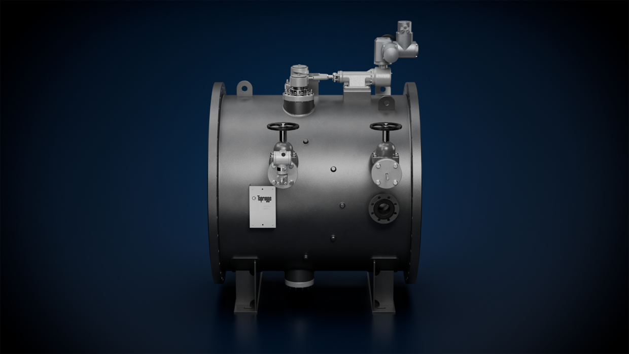
The overall system
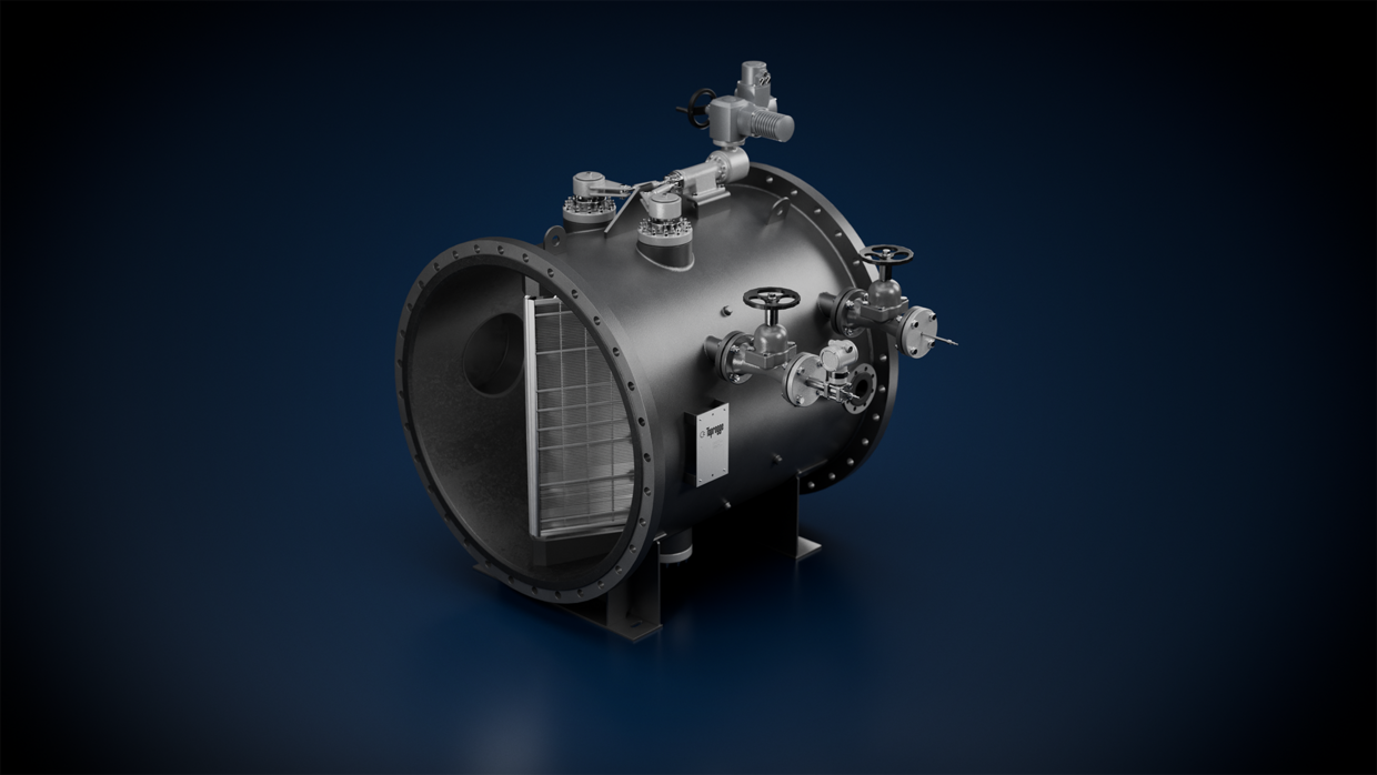
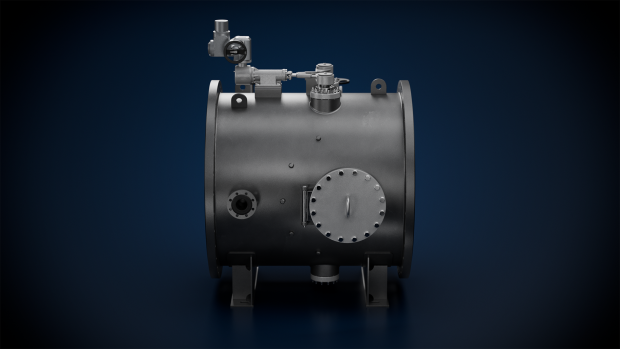
The D2 strainer is a key component of Taprogge’s continuous tube cleaning system. It is installed in the outlet region of the heat exchanger and separates the cleaning balls from the water flow after they have passed through and cleaned the condenser tubes. After exiting the strainer, the balls reach the ball recirculation unit. They are then fed back to the cooling water flow via the ball injection device on the inlet side of the heat exchanger. They then pass through the condenser tubes and make their way back to the strainer.
This creates a closed ball circuit for continuously cleaning the heat exchanger tubes. A programmable logic controller regulates the processes required for system operation and provides reliable information about the system status.

Technical design
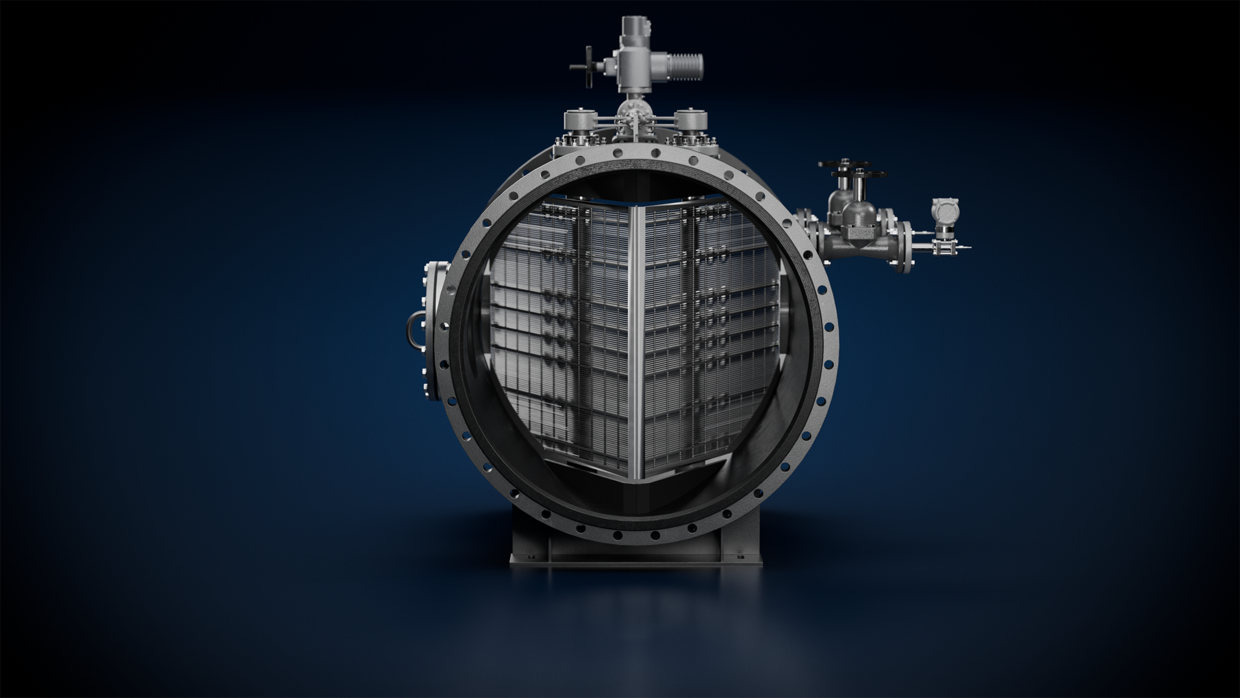
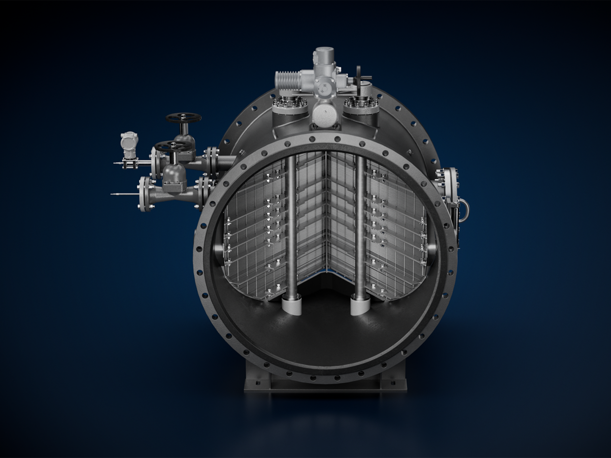
- Two hydrodynamically optimized, backwashable strainers
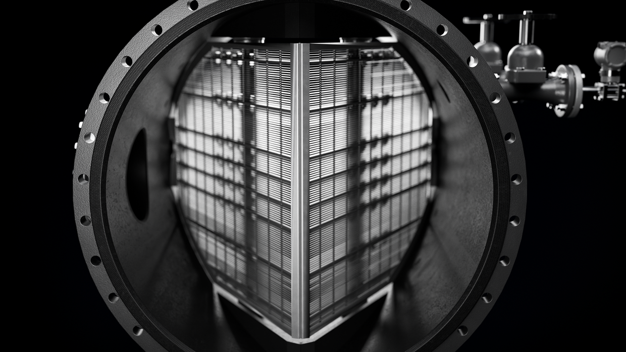
- Roof-shape design with a short installation length
- Induced secondary flows for reliably separating the balls
- Design individually optimized to the hydraulic conditions and cleaning ball types
Financial benefits
The continuous cleaning ensures a consistently high heat transfer rate in the heat exchanger. In power plant applications, this can typically reduce the primary energy demand by around 1–2%. In many projects, the cleaning system pays for itself within just 1–2 years of operation. Manual or chemical heat exchanger cleaning is not required and unplanned shutdowns are avoided.
Project integration
In combination with a Taprogge High-Performance Debris Filter, the cleaning system helps to keep the heat transfer rate stable if it is operated according to the manual.
How it works
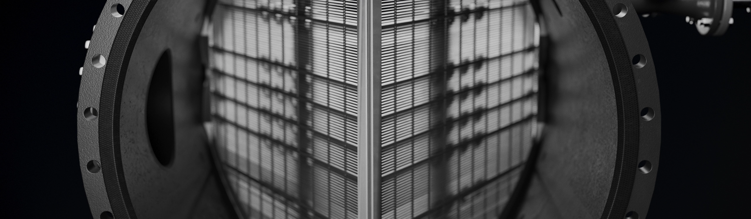
The water flows through two semi-elliptical screens arranged in the shape of a roof, which separate the cleaning balls and feed them to the recirculation system. The flow-optimized geometry minimizes pressure losses. Induced vortices help to reliably extract the balls, even in areas of weaker flow.
Key technical data:
| Volume flow: | 4,000–90,000 m³/h |
| Connection diameters: | DN 800–DN 3 600 |
| Housing: | Rubber-lined steel |
| Temperature: | Up to 80 °C |
| Control: | Programmable logic controller (PLC) |
| Options: | Monitoring of ball circulation and ball oversize |
| Special designs: | ATEX-compliant variants for areas at risk of explosion upon request |
| Systems delivered: | 9440 |
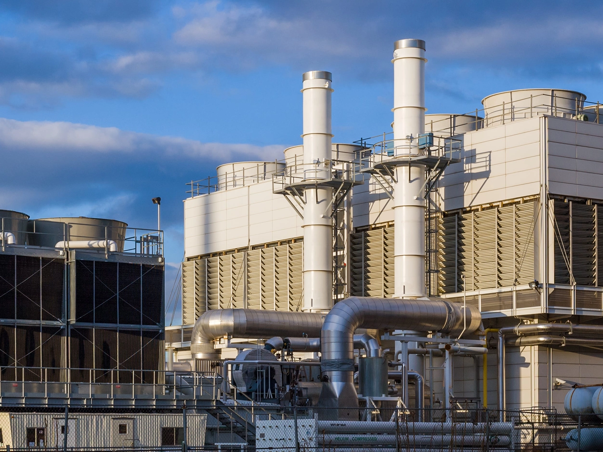
Typical applications include the following
- Steam turbine condensers in power plants
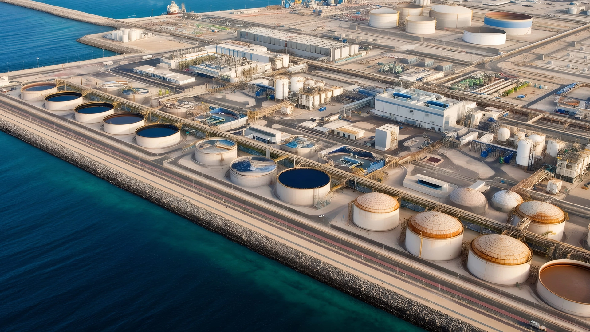
- Evaporators in thermal seawater desalination
- Large-scale shell-and-tube heat exchangers